
How to Install Magnetic Track Lights Like a Pro: A Complete Guide for Commercial Projects
Installation Guide
Magnetic track lighting installation is not a DIY craft project. In commercial environments, it is engineered infrastructure that demands precise coordination between electrical, ceiling, and lighting trades. This guide shows you how to plan, execute, and commission a magnetic track system — from ceiling assessment and voltage planning to module alignment and final handover. Whether you are a project buyer sourcing from an OEM lighting manufacturer or a contractor installing your first commercial system, the sequence matters.
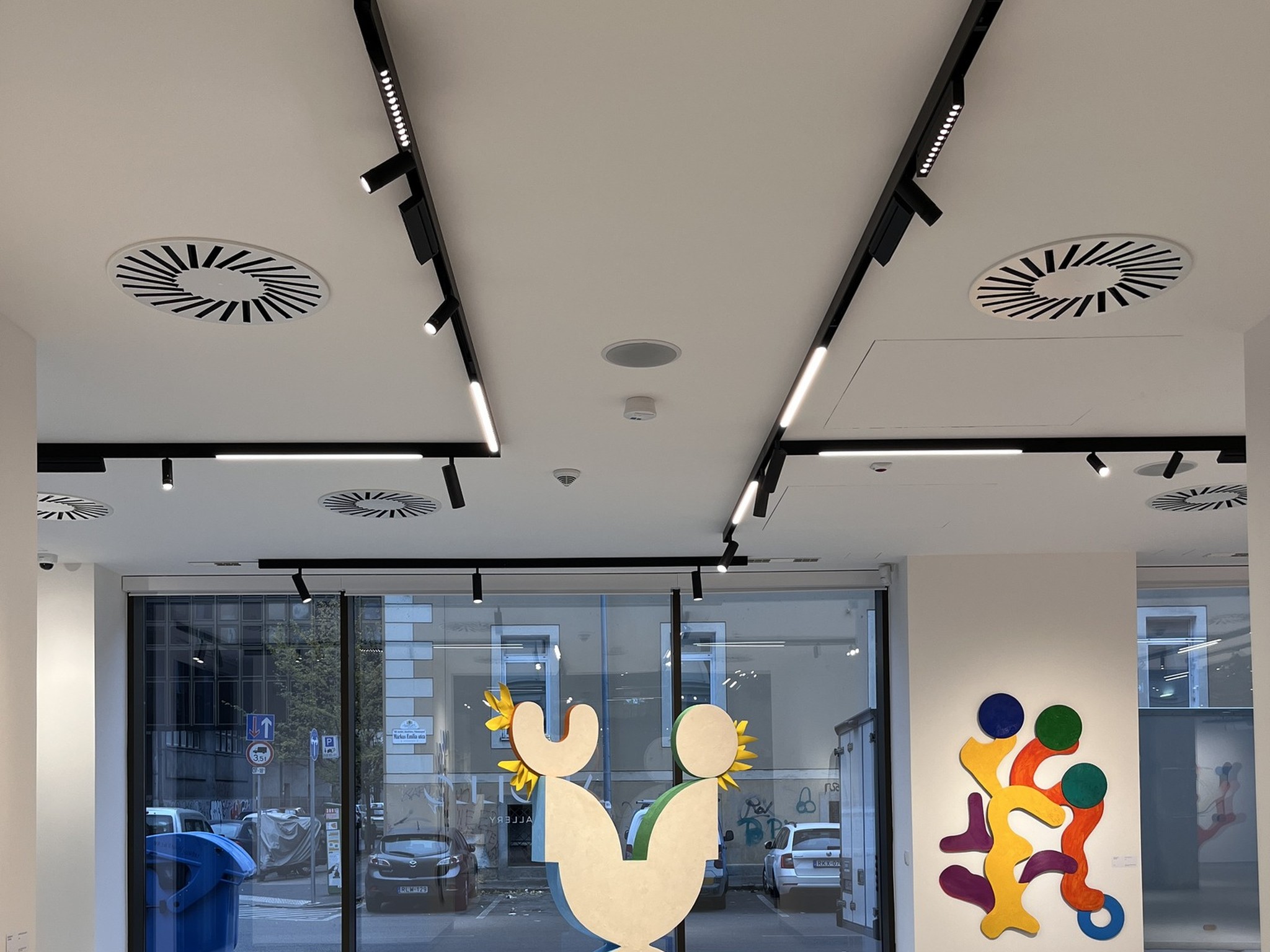
What Is Magnetic Track Lighting Installation (And What Makes It Different)?
Magnetic track lighting installation is the process of mounting a low-voltage DC track rail, connecting it to a remote AC-DC driver, and attaching interchangeable lighting modules via magnetic mechanical coupling. Unlike fixed downlight installation — where every fixture position is permanent — magnetic track installation creates a flexible infrastructure that accepts module changes without tools or ceiling damage.
The critical difference is voltage architecture. The track rail carries 48V or 24V DC, not mains AC. The driver sits remotely in a ceiling void or electrical closet. This means your installation splits into two distinct phases: structural track mounting (ceiling trade) and electrical energization (electrical trade). Misunderstanding this split is the root cause of most field failures.
The 4 Components You Will Install
Every installation involves these four elements. Know them before you open the ceiling.
Track Rail: An extruded aluminum profile housing copper conductors. The profile geometry — 20mm slim or 35mm commercial-grade — determines load capacity and module compatibility. View our track rail profiles and load ratings →
Driver: The AC-DC power supply converts mains voltage to 48V or 24V DC. It mounts remotely, not on the track. Driver placement dictates cable run lengths and voltage drop calculations.
Modules: Spot, linear, wall-washer, grille, and pendant units attach magnetically and draw power through contact pins. Each module is self-contained with its own micro-driver and LED array.
Connectors & Accessories: L, T, and X connectors turn corners and branch circuits. End caps terminate runs. Suspension kits hang track from high ceilings. Not all brands share connector standards — verify ecosystem lock-in before installation begins.
| Component | Installer's Responsibility | Critical Check |
|---|---|---|
| Track Rail | Ceiling contractor / Main contractor | Profile alignment ±2mm over 3m; backing plates at joints |
| Driver | Electrical contractor | Voltage match (24V or 48V); protocol compatibility |
| Modules | Lighting technician / Facilities | Voltage match; magnetic seating verified; no forced insertion |
| Connectors | Ceiling contractor | Geometry match to track profile; conductor continuity tested |
3 Installation Methods Compared: Recessed, Surface & Suspended
Before you order track, you must choose an installation method. The method is not an aesthetic afterthought — it determines ceiling coordination, labor cost, structural requirements, and whether the project needs a specialist ceiling contractor.
| Factor | Trimless Recessed | Surface Mounted | Suspended |
|---|---|---|---|
| Ceiling Type | Plasterboard only | Concrete, plasterboard, or existing surface | High ceilings, atriums, exposed structures |
| Install Phase | During ceiling construction | Post-construction or retrofit | Post-construction |
| Skill Level | High (plaster coordination) | Medium | Medium (structural verification required) |
| Visual Result | Track flush with ceiling plane | Track visible as design element | Floating linear element |
| Reconfiguration | Modules only (track fixed) | Modules only (track fixed) | Modules + height adjustable |
| Cost per Meter | Highest (labor + material) | Mid-range | Mid-range + structural hardware |
| Best For | Premium retail, galleries, luxury hospitality | Offices, retrofit, industrial-style spaces | Restaurants, lobbies, double-height retail |
Trimless recessed delivers the cleanest aesthetic but demands coordination during the plasterboard phase. Surface-mounted is the fastest route for retrofits. Suspended adds vertical design flexibility but requires structural load verification. Choose based on ceiling reality, not catalog photography.
Pre-Installation Planning: The Checklist That Prevents Callbacks
Most installation failures originate in planning, not execution. Use this six-point checklist before any material arrives on site.
Step 1 — Verify Ceiling Substrate and Void Depth
Plasterboard ceilings offer the most flexibility. Concrete ceilings eliminate recessed options unless you cut channels — rarely cost-effective. Measure void depth: remote drivers need 80–120mm clearance for heat dissipation. If your ceiling void is shallow, plan driver placement in adjacent closets or bulkheads.
Step 2 — Calculate Total Load and Circuit Capacity
Sum the wattage of all planned modules, add 20% margin, and verify against circuit breaker capacity. A 48V system with 25 modules at 15W each draws 375W. At 48V, that is 7.8A. On a 10A circuit, you have margin. On a 6A circuit, you do not.
Example: 24 modules × 18W = 432W. 432W ÷ 48V × 1.2 = 10.8A. You need a 16A breaker, not 10A.
Step 3 — Map Driver Locations and Cable Runs
Drivers must be accessible for maintenance. Place them in ceiling voids with removable panels, electrical closets, or junction boxes. Calculate cable run length from driver to track feed point. On 48V systems, voltage drop is manageable up to 20 meters on 2.5mm² cable. On 24V systems, keep runs under 10 meters or increase conductor size.
Step 4 — Confirm Module Ecosystem Completeness
Your specification may require spot, linear, wall-washer, grille, and pendant modules. Verify that your manufacturer produces every type you need. Ecosystem gaps force hybrid systems — and hybrid systems fail. Browse our full module ecosystem →
Step 5 — Check Dimming Protocol Compatibility
The driver determines dimming capability — 0-10V, DALI-2, Bluetooth Mesh, or Zigbee. Confirm the control system is specified and wired during rough-in. Retrofitting DALI bus wiring after ceiling closure is expensive.
Step 6 — Order Pre-Production Samples
Before bulk delivery, install a 2-meter sample track with one of each module type. Verify mechanical fit, magnetic holding force, finish match, and photometric output. This 30-minute exercise prevents bulk-order surprises.
Step-by-Step Magnetic Track Lighting Installation
This sequence applies to all three methods — recessed, surface, and suspended — with method-specific notes where required. Follow the order. Skipping steps creates the failures we document in the next section.
Step 1 — Layout, Marking, and Leveling
Transfer the lighting design to the ceiling using laser levels. Mark track centerlines, feed points, and driver locations. For trimless recessed, mark plasterboard cut lines with 2mm shadow gaps. Verify that track runs avoid sprinkler heads, smoke detectors, and HVAC diffusers by at least 150mm.
Critical tolerance: Track must be level within ±2mm over 3 meters. Any waviness telegraphs through the finished ceiling or creates visible gaps in surface-mounted installations.
Step 2 — Track Mounting
Trimless Recessed: Install backing plates at all joints and feed points before plasterboard goes up. Secure track profiles to backing with screws at 300mm centers. Apply plaster stopping flush to track edges. The track face must sit exactly flush with the finished plaster plane — not recessed, not proud.
Surface Mounted: Mark and drill anchor points at 400mm centers. Use appropriate anchors for the substrate — expansion anchors for concrete, toggle bolts for hollow ceilings. Apply silicone gasket between track and ceiling to prevent dust infiltration. Torque screws to manufacturer specification; overtightening deforms the profile.
Suspended: Install ceiling anchors rated for 5× the total track load including modules. Attach suspension cables at 1.2–1.5 meter intervals — never exceed 1.5 meters on 35mm commercial track. Adjust height with turnbuckles and verify level after 24 hours (cables stretch initially).
Step 3 — Wiring and Driver Connection
This is the highest-risk phase. The electrical contractor must:
- Run mains AC to the driver location only — never to the track rail.
- Connect driver output (48V or 24V DC) to the track feed point using the manufacturer's specified cable type and gauge.
- Observe polarity. Reversed polarity will not damage modules in most systems, but they will not illuminate.
- Install the driver in an accessible location with adequate ventilation. Ambient temperature around the driver must not exceed 40°C continuous.
- Label the circuit breaker: "48V DC Magnetic Track — Do Not Connect AC."
Dimming wiring: For DALI-2 systems, run the DALI bus in parallel to the power cable. Use DALI-specified cable (twisted pair, 1.5mm² minimum). Separate DALI bus from mains cable by 50mm to prevent interference.
| Wire Segment | Voltage | Cable Spec | Max Run |
|---|---|---|---|
| Mains to Driver | 230V AC | 2.5mm² LSOH per local code | Per electrical code |
| Driver to Track (48V) | 48V DC | 2.5mm² twin-core flex | 20 meters |
| Driver to Track (24V) | 24V DC | 4.0mm² twin-core flex | 10 meters |
| DALI Bus | 16V DC signal | 1.5mm² twisted pair | 300 meters total bus |
Step 4 — Module Installation and Alignment
With power off, attach modules to the track. The magnetic force will pull the module into position — guide it gently until contact pins seat in the conductor strip. You should feel a distinct mechanical click or resistance when properly seated.
Rotate and position each module according to the lighting design. Spot modules need aiming; linear modules need leveling with adjacent units. For museum and retail projects, use a digital inclinometer to verify spot module angles — visual estimation is not accurate enough.
Seating verification: Gently tug each module after installation. It should not release without deliberate downward pressure on the release mechanism. Loose modules indicate damaged pins or track debris.
Step 5 — Power-On and Initial Testing
Energize at 50% load first. Check for arcing sounds, abnormal heat at connections, or flicker. Use a thermal camera if available — connection points should not exceed 45°C after 30 minutes. Then bring to full load and verify:
- All modules illuminate at full output.
- No visible flicker (test with smartphone slow-motion video at 240fps).
- Dimming curve is smooth from 100% to 1%.
- DALI-2 modules respond to individual addressing.
- Emergency modules switch correctly during power interruption tests.
Wiring, Drivers & Voltage Planning: The Technical Core
Installation quality lives or dies in the wiring. This section covers the decisions that separate professional results from expensive callbacks.
48V vs 24V: Which Voltage Should You Install?
The voltage choice affects every wiring decision. Install 48V for commercial projects with track runs over 10 meters or module counts exceeding 15 per feed. Install 24V only for small-format residential or boutique retail where safety regulations demand lower touch voltage.
Never mix voltages. A 24V module on a 48V track will fail within minutes due to overvoltage. A 48V module on a 24V track will underperform or not illuminate. Label every component — track, driver, and module — with voltage rating during unpacking.
Driver Sizing and Placement Rules
Oversize the driver by 20% minimum. A 400W load needs a 480W driver, not 400W. This margin accommodates module additions, voltage sag under load, and driver longevity.
Place drivers where air can circulate. Enclosed junction boxes without ventilation reduce driver lifespan by 30–40%. If the only available space is a small void, add a ventilation grille or specify a driver with external heat sinking.
5 Installation Mistakes That Destroy Systems (And How to Avoid Them)
Our field team has commissioned over 200 magnetic track installations since 2020. These are the five errors that generate the most expensive callbacks — in frequency order.
Mistake 1 — Running Mains AC to the Track Rail
A contractor in Lisbon treated the magnetic track like a traditional mains-voltage track. He ran 230V AC directly to the rail. Every module failed within 40 minutes. Total replacement cost: €4,200 plus emergency air freight.
Prevention: The track is a DC bus. The driver converts AC to DC upstream. Label the track "48V DC" during delivery. Require the electrical contractor to submit a single-line diagram showing driver placement before rough-in.
Mistake 2 — Installing Trimless Track After Plaster Finishing
A Copenhagen gallery installed trimless track into a finished plaster ceiling. The result: visible gaps, waviness, and a 6mm corner misalignment that required full plaster removal. Repair cost: €3,800.
Prevention: Trimless track is a ceiling-system component, not a retrofit product. Coordinate with the ceiling contractor during construction. Specify ±2mm leveling tolerance. Inspect alignment before plaster stopping begins.
Mistake 3 — Exceeding Cable Spacing on Suspended Systems
A Dubai restaurant used 2.8-meter cable spacing on a 35mm track — nearly double the 1.5-meter maximum. Under module load, the track sagged visibly and transmitted HVAC vibration to the spots.
Prevention: Follow manufacturer cable spacing precisely. Add sway restraints in high-airflow environments. Verify structural load capacity with an engineer before installation.
Mistake 4 — Ignoring Voltage Drop on Long Runs
A Berlin office installed 18 meters of 24V track on a single feed using 1.5mm² cable. Modules at the far end dimmed progressively — 100% at the feed, 60% at the terminus. The fix required a second driver and mid-run power injection.
Prevention: Calculate voltage drop before installation. On 24V systems, use 4.0mm² cable for runs over 8 meters or split the run into two feeds. On 48V systems, 2.5mm² cable handles up to 20 meters comfortably.
Mistake 5 — Forcing Incompatible Modules
A Warsaw retail rollout mixed modules from two brands with nearly identical product names. Connector geometry differed by 1.2mm. Forced insertion bent contact pins, creating intermittent connections that failed three months post-opening.
Prevention: Verify ecosystem compatibility before ordering. If sourcing from an OEM lighting manufacturer, request mechanical fit samples for all module types. Do not assume that "standard" 48V modules are interchangeable across brands.
Commissioning, Testing & Handover Standards
Installation ends when the system is commissioned, documented, and handed over — not when the lights turn on. This section provides the commissioning sequence our field engineers use on OEM projects.
Pre-Power Inspection
Before energizing, verify:
- Track alignment and level within ±2mm over 3 meters.
- All modules seat firmly with no visible gap between module base and track profile.
- Driver labeling matches track voltage.
- Emergency circuit integrity (if applicable).
- All connector joints show continuity on multimeter test.
Initial Energization and Photometric Verification
Power on at 50% load. Check for arcing, heat, or communication errors on DALI networks. Then program default scenes: day, evening, cleaning, and emergency. Measure illuminance at designated points with a calibrated lux meter. Compare against design calculations — variance should not exceed ±10%.
Handover Documentation
Deliver to the client:
- As-built drawings showing track runs, driver locations, and circuiting.
- Driver configuration files and scene setting backups.
- Warranty certificates for track (typically 5 years) and modules (typically 3–5 years).
- Maintenance schedule: annual module inspection, driver filter cleaning, and contact pin inspection.
Which Installation Method Fits Your Project? A Decision Table
Use this table to guide stakeholder conversations. The answer depends on ceiling type, budget, aesthetic priority, and change frequency — not on what looks best in a catalog.
| If Your Project Has... | Choose | Why |
|---|---|---|
| Plasterboard ceiling + premium aesthetic requirement | Trimless Recessed | Flush finish, invisible hardware, highest visual impact |
| Concrete ceiling + retrofit timeline | Surface Mounted | No channel cutting, fastest install, no plaster repair |
| Ceiling height > 3.5m + design statement | Suspended | Vertical positioning, adjustable height, dramatic effect |
| Quarterly layout changes + operational cost focus | Any method (modularity is inherent) | All methods allow tool-free module swap; choose by ceiling |
| Tight first-cost budget + static layout | Surface Mounted or Fixed Downlight | Trimless recessed carries 20–30% labor premium |
Final Checklist: Did You Install It Like a Pro?
Professional magnetic track lighting installation comes down to sequence, verification, and documentation. Before you sign off, confirm these items:
- Voltage verified: Track, driver, and modules share the same voltage rating — 24V or 48V, never mixed.
- Alignment verified: Track level within ±2mm over 3 meters. No waviness, no gaps, no proud edges.
- Load verified: Circuit capacity exceeds total module load by 20% minimum.
- Dimming verified: Protocol matches control system. Smooth operation from 100% to 1%.
- Emergency verified: If required, emergency modules or central battery interfaces function correctly.
- Documentation delivered: As-builts, driver configs, warranty certs, and maintenance schedule handed to facilities.
Magnetic track lighting installation is not complex, but it is unforgiving of skipped steps. The 30 minutes you spend on sample validation and load calculation will save days of callbacks and thousands in remediation.
FAQs About Magnetic Track Lighting Installation
Can I install magnetic track lighting myself, or do I need a certified electrician?
The track mounting (recessed, surface, or suspended) can be performed by a qualified ceiling contractor. However, all electrical connections — mains to driver, driver to track, and control wiring — must be completed by a certified electrician per local electrical codes. The track carries low-voltage DC, but the driver handles mains AC. Never attempt driver wiring without proper certification.
What is the maximum track length I can run on a single driver feed?
On 48V systems with 2.5mm² cable, maximum track run is 15–20 meters per feed with 20–30 modules. On 24V systems, limit runs to 8–10 meters or increase cable gauge to 4.0mm². Exceeding these limits causes voltage drop, resulting in dimmed output at the far end of the track.
Can I mix different module types on the same track during installation?
Yes — spot, linear, wall-washer, grille, and pendant modules from the same manufacturer can share one track if they match the system voltage and control protocol. You cannot mix modules from incompatible brands due to connector geometry differences. Verify ecosystem completeness before specifying.
How do I prevent modules from falling out of the track?
Commercial-grade magnetic track systems use magnetic force combined with mechanical locking. When properly seated, modules resist gravitational pull and moderate vibration. Ensure the track is clean (no plaster dust or debris on conductors) and that modules click into position with distinct mechanical resistance. If a module feels loose, remove it and inspect the contact pins for bending.
What ceiling height is required for suspended magnetic track installation?
Suspended track works at any ceiling height but is most effective above 3.5 meters where surface-mounted fixtures would appear visually heavy. Cable drop length is typically 0.5–1.5 meters. In spaces below 2.8 meters, surface-mounted or recessed track is usually more appropriate. Always verify structural load capacity with an engineer.
Can magnetic track lighting be dimmed, and what protocol should I specify during wiring?
Yes. The dimming protocol is determined by the remote driver, not the track or module. Options include 0-10V analog, DALI-2 digital, Bluetooth Mesh, and Zigbee 3.0. For commercial projects requiring scene management and energy monitoring, specify DALI-2 during the electrical rough-in phase. Retrofitting DALI bus wiring after ceiling closure is costly.
What certifications should the installed system carry?
Minimum: CE (Europe), ENEC (safety), RoHS (hazardous substances), and ISO 9001 (quality management). For premium or regulated projects: TÜV GS, SAA (Australia), and relevant local electrical approvals. Request certificate numbers and verify validity on issuer databases before installation begins.
Do you provide installation support or commissioning for large projects?
Yes. As an OEM lighting manufacturer, we provide installation guidelines, sample validation, remote technical support, and on-site commissioning for projects exceeding 500 modules. Our engineering team can review your single-line diagrams and ceiling sections before construction begins. Contact our project team →
Need specification support or custom magnetic track systems for your next project?
Get our free Magnetic Track Installation Checklist, or talk to our engineering team about OEM custom lighting solutions tailored to your project volume, ceiling type, and control protocol requirements.
How to Install LED Recessed Downlights in Commercial Spaces: A Contractor's Guide
Magnetic Track Lighting Systems for Commercial Projects: A Complete Guide to Benefits, Specifications & Implementation